What is the purpose of a context diagram
Context diagrams show the interactions between a system and other actors (external factors) with which the system is designed to interface. System context diagrams can be helpful in understanding the context which the system will be part of.
Why do we use context diagrams?
The context diagram is used to establish the context and boundaries of the system to be modelled: which things are inside and outside of the system being modelled, and what is the relationship of the system with these external entities. … It identifies the flows of information between the system and external entities.
What is context diagram give an example?
Context DiagramData Flow Diagram· Datastores are collections of information.· The data stores consist of databases, computer files, and paper files.· It models a new set of activities and functions.· It models a new system of implementation.
What is the use of a context diagram in DFD?
DFD Level 0 is also called a Context Diagram. It’s a basic overview of the whole system or process being analyzed or modeled. It’s designed to be an at-a-glance view, showing the system as a single high-level process, with its relationship to external entities.What is a context diagram quizlet?
Context Diagram. An analysis model that illustrates product scope by showing the system in its environment with the external entities (people and systems) that give to and receive from the system.
What are entities in a context diagram?
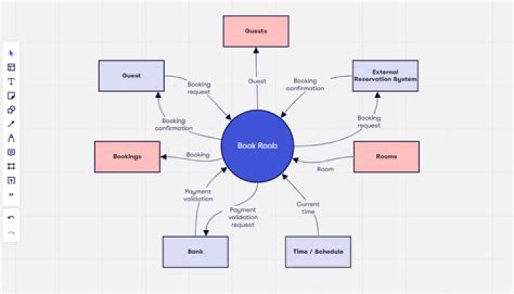
Context diagrams can be developed with the use of two types of building blocks: Entities (Actors): labeled boxes; one in the center representing the system, and around it multiple boxes for each external actor. Relationships: labeled lines between the entities and system.
What is a context diagram in business analysis?
A context diagram is a graphic design that clarifies the interfaces and boundaries of the project or process at hand. It not only shows the process or project in its context, it also shows the project’s interactions with other systems and users.
What is the difference between DFD and context diagram?
A Data flow diagram (DFD) is a much more complex representation of a context diagram. DFD show a further level of detail not shown in the context diagram. DFD’s identify the source of data, its flow between processes and its destination. It along also shows data generated by the system.When drawing a context diagram standardized names should be used?
When drawing a context diagram, standardized names should be used within each set of symbols. Spontaneous generation, black holes, and gray holes are impossible logically in a data flow diagram. In data flow diagrams (DFD), systems analysts call an entity that supplies data to the system a sink.
How do you create a context diagram?- Select the “Data Flow” shape library or choose a template. …
- Place your system in the center of your context diagram. …
- Add all external entities around your system. …
- Add and specify data flows between your system and external entities. …
- Share your system diagram with team members and stakeholders.
What should be included in a system diagram?
System Diagrams are more than process flow charts. They include feedback loops and other factors that influence how decisions are made, including attitudes, perceptions, and behaviors. … It is also important to understand the true leverage points to improve a system, which probably won’t be obvious.
How do I create a context diagram in Word?
- In Word, go to Insert > Illustrations > Shapes. A drop-down menu will appear.
- Add shapes and lines to build your DFD.
- Add text with a text box. Go to Insert > Text > Text box.
- Save your document.
What is the difference between a context diagram and diagram 0 also known as a DFD Level 1?
Level 0 data flow diagrams show a single process node and its connections to external entities. Level 1 DFDs are still a general overview, but they go into more detail than a context diagram. In a level 1 data flow diagram, the single process node from the context diagram is broken down into subprocesses.
What is meant by an exploded DFD?
The DFD is designed to show how a system is divided into smaller portions and to highlight the flow of data between those parts. This context-level Data flow diagram is then “exploded” to show more detail of the system being modeled” [Data model.
What does a data collection symbol mean?
Data collection symbol – Signifies information collected within a business process. Data storage symbol – Represents the ability to store or access data that’s associated with a business process.
Why is it important for the business analyst to define the system context?
Precisely because a context diagram offers a concise high-level overview, it sets expectations among project stakeholders and forces business analysts to methodically and thoroughly assess requirements and the resources necessary for their implementation.
What is the relationship between context diagram and diagram 0?
The context diagram provides different views of information system. Diagram 0 is used to provide insight view of an info system represents internal process, entities, data flow, and data storage.
What is a stakeholder context diagram?
In general, a Context Diagram can be used to examine: An existing system (to help determine what users and entities it interacts with) Stakeholder Identification. A conceptual solution system (to help determine what users and entities it will interact with)
What is a content diagram?
The Content diagram is an extension of UML notation. The purpose of the Content diagram is to generate or represent a project structure (diagrams) and relations between them. The Content table works as a table of contents for a project. The Content Shape creates a table of contents of all diagrams of the project.
When a context diagram is expanded into data flow diagram?
Data stores are shown in a context diagram because data stores are external to the system. When a context diagram is expanded into data flow diagram (DFD) diagram 0, all the connections that flow into and out of process 0 must be retained. A method is like a blueprint, or template, for all the objects within a class.
When a DFD is exploded the higher level diagram is called the child diagram and the lower level diagram is referred to as the parent diagram?
A data flow diagram (DFD) does not show the external entities that provide data to the system or receive output from the system. … When a data flow diagram (DFD) is exploded, the higher-level diagram is called the child diagram, and the lower-level diagram is referred to as the parent diagram.
What is data flow diagram in system analysis and design?
A data flow diagram (DFD) is a graphical or visual representation using a standardized set of symbols and notations to describe a business’s operations through data movement. They are often elements of a formal methodology such as Structured Systems Analysis and Design Method (SSADM).
What is context diagram in system analysis and design?
A system context diagram (SCD) in software engineering and systems engineering is a diagram that defines the boundary between the system, or part of a system, and its environment, showing the entities that interact with it. This diagram is a high level view of a system. It is similar to a block diagram.
What is context diagram PMP?
Context diagrams are visual tools that depict the scope of the product showing the business system and how it relates and interacts with the other systems as well. … It helps project managers understand the flow of the project’s system as it depicts the scope in abstraction.
How do you explain a system diagram?
A system diagram is a simple and very high level description of a system that exists or needs to be built. It is a simple diagram that can be drawn collaboratively in little time. It can help a team get a clear, complete, and common understanding of a system.
What is a system diagram design?
A system diagram is a visual model of a system, its components, and their interactions. With supporting documentation, it can capture all the essential information of a system’s design. There are many variations of diagramming style that all fall under this rubric.
How do you create a workflow diagram in Word?
- Open a blank document in Word.
- Add shapes. To begin adding shapes to your flowchart in Word, you have two options. …
- Add text. Add text to a SmartArt graphic by clicking the filler text and begin typing. …
- Add lines. …
- Format shapes and lines.
What is included in a process flow diagram?
Process flow diagram (PFD) illustrates the arrangement of the equipment and accessories required to carry out the specific process; the stream connections; stream flow rates and compositions; and the operating conditions.